Printing helper functions
Alright so at the beginning I would write to address 0xb8000 because that is the BGA text offset in the video memory mapped region of memory as shown here:
0x00000000 – 0x0009FFFF : Conventional RAM (usable)
0x000A0000 – 0x000BFFFF : Video memory / VGA text mode
0x000C0000 – 0x000FFFFF : BIOS ROM / system ROM
0x00100000 – 0x07FFFFFF : Extended RAM (default 128 MB, configurable with -m)
0x08000000 – 0x3FFFFFFF : Extended RAM continuation (depends on -m size)
0x40000000 – 0xBFFFFFFF : PCI hole / MMIO for PCI devices
0xC0000000 – 0xCFFFFFFF : PCI device MMIO regions
0xD0000000 – 0xDFFFFFFF : Optional MMIO / device regions
0xE0000000 – 0xEFFFFFFF : VGA MMIO / other device regions
0xF0000000 – 0xFFFFFFFF : BIOS / reserved legacy system space
Offsets in video memory:
0x00000 – 0x0FFFF : VGA graphics modes (legacy / planar)
0x10000 – 0x17FFF : Monochrome text mode (MDA)
0x18000 – 0x18F9F : Color text mode framebuffer (80×25)

text_offset = (row * 80 + col) * 2
char = text_offset
attr = text_offset + 1
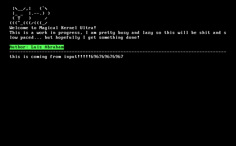
So with this we can create helper functions that will just add an offset, go to a new line, change colors, etc. I created a set area for a menu where it will hold a little ASCII cat and it always stays there, even when I push all my text up, it will stay there. I also made some functions that will print hexadecimal values to the screen for whenever I want to debug and such. Very nice and neat!
Maybe one day I will set up actual graphics… LMAO propably not…
Interrupts
Interrupt Descriptor Table (IDT) and Interrupt Service Routines (ISRs)
Alright now we get to the first real and important feature in a kernel… interrupt handling.
This actually is not too bad, I have worked with ARM interrupts and the GIC (Generic Interrupt Controller) before so this was a pretty smooth process. The main difference between what I worked on in ARM and x86_64 is that usually when there is a hardware IRQ in ARM (or at least with what I have worked with), the program will immediately run the code in offset 0x18, which usually is a 4-byte branch instruction to the IRQ handler.
On the contrary, with intel there is an idea of an IDT and a register that holds a pointer to it. When an interrupt fires, rather than going to a fixed address, the CPU will actually index into the IDT held in that register based off of the IRQ number. There it will hold a pointer to the interrupt handler function (aka ISR) and also other descripting bits since each entry is 128 bits. This is stated here.
Anyways I ended up snatching the helper functions from this osdev post since I know what to do and it already does it for me.
typedef struct {
	uint16_t    isr_low;      // The lower 16 bits of the ISR's address
	uint16_t    kernel_cs;    // The GDT segment selector that the CPU will load into CS before calling the ISR
	uint8_t	    ist;          // The IST (interrupt stack table) in the TSS that the CPU will load into RSP; set to zero for now
	uint8_t     attributes;   // lower nibble = gate type (0xE specifies interrupt gate) next bit is 0, next 2 bits are priv levels and last bit is present bit (set to 1 to enable)
	uint16_t    isr_mid;      // The higher 16 bits of the lower 32 bits of the ISR's address
	uint32_t    isr_high;     // The higher 32 bits of the ISR's address
	uint32_t    reserved;     // Set to zero
} __attribute__((packed)) idt_entry_t;

// this is for the IDT register
typedef struct {
	uint16_t	limit;
	uint64_t	base;
} __attribute__((packed)) idtr_t;
Programming the Programmable Interrupt Controller (PIC)
The PIC helps us handle multiple interrupts by only having one connection to the CPU but having multiple interrupt lines (8 to be exact). So an interrupt from an external peripheral will fire, and then it will go to the PIC which will handle it in terms of checking if it is masked or not along other stuff, and then it will pick one IRQ to then tell the CPU to handle once it is available to do so.
In the machine that we are using, the timer is in IRQ line 0 and the keyboard is in IRQ line 1, which are the ones that we will need in the near future. As well as there is another cascaded PIC that we will also need to program.
Programming it is not too crazy, all we want to do is remap it so that IRQ line 0 actually maps to ISR 0x20 because we want the first 32 entries of the IDT to be exceptions. For that I took a helper function from osdev that will do that for me, obviously making sure I understand what is going on. I have had to read datasheets for my Microcomputer Systems class that are similar to this so I know how to do it I just want to take the easier path if I can…
Getting keyboard input
Now that we got everything set up, we can now add an ISR on index 0x21 for the keyboard interrupt (since it is in IRQ line 1). This function will be an assembly stub function that will do the following:
- push all registers to the stack
- call the C function to handle the interrupt
- pop the registers back out
- call iretq (interrupt return)
This is so that way when the interrupt is handled, it does not mess with whatever was going on before it. We dont need to worry about CS, SS, RFLAGS, RSP, and RIP being pushed to the stack since that is what is done automatically and then popped back out in the IRETQ call (not in that order, unless I accidentally did it in the correct order).
In the keyboard interrupt handler, I read the output buffer flag in bit 1 from the status buffer in port 0x64. If it is set then that means that we got a scancode to read. The scancodes don’t directly map out to ASCII values so I asked ChatGPT to generate me a lookup table that would map them out, again I could do this by hand… but why would I do that?
From there I would print to the screen whatever character is read from the input and then I would send out an End of Interrupt (EoI) back to the PIC to tell it that I am ready to take in another interrupt. Here is the handler code, it is pretty basic:
void keyboard_int_handler() {
    // status register bit 1 = output  buffer status
    if ((inb(0x64) & 1) == 0)
        return;

    uint8_t scancode = inb(0x60); // read the data port

    // ignore key releases
    if (scancode & 0x80) {
        scancode &= 0x7F;
        if (scancode == 0x2A || scancode == 0x36)
            shift = false;
    }
    else {
        if (scancode == 0x2A || scancode == 0x36) {
            shift = true;
            PIC_sendEOI(1);

            return;
        }

        print_char(translate_scancode_set_1(scancode, shift));
    }

    PIC_sendEOI(1);
}
Now from this we got IO working!!!!